Quantcast
Channel: Internet - Ethernet - LAN Projects - PIC Microcontroller
Viewing all 60 articles
Browse latest View live

Wireless controlled lightdimmer using PIC12F629

$
0
0

The meaning from this design is to build it in -i.e. a shaded lamp- and to switch this lamp on and off the normal way, just like it was switched before the dimmer was build in, then you could by exception dimming the lamp more or less with your TV remote control.
When you switch the power on there will follow a soft-start till the lamp burns at the previously adjusted dim level.
With the ‘0’ button in TV mode you can dim the lamp, turn more and less bright.

light dimmer
The remote control should send more then one RC5-signal per button-press seeing that the first one is ignored, this does imply that when the remote button is pressed a short time, there nothing happens.
With the P+ and P- button from a system at choice you can adjust the maximum and minimum dim-levels and with the ‘1’ button the start-up brightness.
The next time when the 230V power is switched on the lamp starts up at the adjusted dim-level.

(Re)adjust the dim-levels:
(only necessary when changing the maximum-, minimum- or start-up- level)
First you should select an unused system on your remote control, i.e. SAT, AMP, VCR2 or DCC mode.

Adjust maximum level: Keep, while switching the power on, the P+ button from the remote control pressed and wait until the lamp burns on desired maximum level.

Adjust minimum level: Keep, while switching the power on, the P- button from the remote control pressed and wait until the lamp burns on desired minimum level. Recommended is to adjust the minimum dim level not to “lamp off” level, because then it’s easy to forget to switch the power off and use unnecessary power.

Adjust start-up level: Keep, while switching the power on, the ‘0’ button from your remote control pressed and wait until the lamp burns on desired level.

Re-adjust the default values (reset): Keep, while switching the power on, the MUTE button from the remote control pressed.

During adjusting the dim-levels, the dim-level changes slower then normal to make adjusting easier.
When letting the button loose and the adjustment is ok, the red- en green LED blinks for a while.
With the -for the dimmer reserved- system selected on the remote control, the P+ (dim-level up) / P- (dim-level down) and button ‘0’ (up/down turn by turn) works too.
Button ‘1’ dims directly to the adjusted start-up level.
Which system on the remote control is choosen doesn’t matter, the ‘0’ button works always in the TV-mode too.

Above described applies to the here downloadable .BAS and .HEX examples, but you can ofcourse modify it to your own wishes.
Keep in mind that a remote control does not always send that what you expected.
The volume from TV, SAT, VCR1 and VCR2 are all the same.
Just as the volumegroup from TAPE, TUNER, CD, etc.
And the ‘0’-‘9′ buttons from system TAPE for example send nothing at all.

See the lists: RC5 system codes and RC5 command codes


For more detail: Wireless controlled lightdimmer using PIC12F629

The post Wireless controlled lightdimmer using PIC12F629 appeared first on PIC Microcontroller.


Wireless 10 channel receiver using PIC16F630

$
0
0

This project can steer 10 different things wireless with the use of a normal TV-remote-control with the RC5 protocol, from manufacters like Philips, Grundig and Marantz.
If the Proton PIC Basic compiler is available, then you can ofcourse change the number of channels.

PIC16F630

Use it as follows:
When ‘TV’ mode is selected on your remote-control, you can with the buttons 0 through 9 on it, steer 10 outputs on and off.
When there is an unused system on your remote-control (SAT, AMP, DCC, VCR2) then the code in the PIC can be changed with the remote-control to another system.
This goes as follows:
Switch the power from the PIC to OFF.
Select an unused system on the remote-control (like SAT, AMP, DCC or VCR2).
Push a button (0-9) on the remote-control and keep it pressed while switching the power from the PICmicro ON.
If the LED blinks a couple of times slow, then the new system is programmed in EEPROM.
Now the buttons 0-9 works only when the remote-control stands in the just programmed system mode.
The LED burns continue while a valid button from a valid system is received and blinks fast when an invalid IR-code is received.

‘System’ means equipment like TV, VCR, TAPE, SAT, etc.
‘Command’ means buttons on the remote like 0-9, I/II, PLAY, STOP, etc.
A push on a button from the RC5 remote-control sends: a header, a togglebit, an extended (7th) command bit, a 5 bit system-code and a 6 bit command code.
When the received system-code is equal to the programmed one in the EEPROM from the PIC, then the command-code is executed.
The programs are based on the 14-pins 16F630, but they can ofcourse make workable for almost every type PIC.
To see what system- and command-code’s your remote-control sends, you can build an other (easy) project: RC5/RC6 codes on a LC-Display
That project displays the IR-code’s on LCD so this project can be extend to steer much more channels wireless (till 127 outputs!) with for example the 74HC595.


For more detail: Wireless 10 channel receiver using PIC16F630

Current Project / Post can also be found using:

  • using microcontroller in receiver

The post Wireless 10 channel receiver using PIC16F630 appeared first on PIC Microcontroller.

NETWORK EQUIPMENT RESETTER using PIC16F628

$
0
0

Introduction

This program is a network power resetter. It controls a solid-state-relay that is in series with 110VAC that supplies power to a satellite internet receiver, various routers, etc. Once every 24 hours it drops power for 10 seconds to allow the receiver and routers to start clean, something that seems to be necessary to keep receivers and routers from “losing themselves” after running too long!

NETWORK EQUIPMENT RESETTER

Features

This is simply an electronic solution with a couple of features, but the same thing can be accomplished by the use of a mechanical “home” timer that drops power once per day, as illustrated in the image below.

Operation

  • Power is dropped automatically for 10 seconds once every 24 hours, starting eight hours after the unit is powered up.

NETWORK EQUIPMENT RESETTER schematic

Code:

/****************************************************************************
NETWORK_RESET_01.C

This program is a network reseter.  It controls a solid-state-relay that
is in series with 110VAC.  It supplies power to a satellite receiver,
various routers, etc.  Once every 24 hours it drops power for 10 seconds
to allow the receiver and routers to start clean.

The LED flashes once per second.

The 24 hour reset occurs eight hours from the time the unit is powered on.
If it is desired to changed that delay, decide how many hours (from now)
that you want the unit to reset.  Press and hold the button for
greater than five seconds, and release it.  The LED will stop flashing.
Immediately press and hold the button until the LED starts flashing.  Count
the flashes as you hold the button.  Release the button when the LED has
flashed the number of hours you want to delay.  Normal operation will
occur after three seconds.

To drop power immediately, press and hold the button for two seconds.

                 +5
                  |
                  14
                ----------
     SW  ----6-|          |-17-- LED
               |          |-18-- SSR
               |          |
               |          |
               |  16F628  |
               |          |
               |          |-13--PROG_CLK
               |          |-12--PROG_DAT
  6MHz XTAL-15-|          |-4---MCLR
       XTAL-16-|          |     GND
                ----------
                     5
                     |
                    Gnd

***************************************************************************/


For more detail: NETWORK EQUIPMENT RESETTER using PIC16F628

The post NETWORK EQUIPMENT RESETTER using PIC16F628 appeared first on PIC Microcontroller.

GSM based Control System by pic microcontroller

$
0
0

GSM based Control System by pic microcontroller implements the emerging applications of the GSM Technology. Using GSM networks, a control system has been proposed that will act as an embedded system which can monitor and control appliances and other devices locally using built-in input and output peripherals.

Remotely the system allows the user to effectively monitor and control the house Appliances and equipment’s via the mobile phone set by sending commands in the form of SMS messages and receiving the appliances status. The main concept behind the project is receiving the sent SMS and processing it further as required to perform several operations. The type of the operation to be performed depends on the nature of the SMS sent. The principle in which the project is based is fairly simple. First, the sent SMS is stored and polled from the receiver mobile station and then the required control signal is generated and sent to the intermediate hardware that we have designed according to the command received in form of the sent message.

GSM based Control System by pic microcontroller

GOALS AND OBJECTIVE

 The project “GSM based Control System by pic microcontroller” at the title suggests is aimed to construct a control system that enables the complete control of the interface on which it is based. General objectives of the project are defined as;

a. To co-ordinate appliances and other devices through Short Message Service (SMS).

b. To effectively receive and transmit data via SMS

c. To eliminate the need of being physically present in any location for tasks involving the operation of appliances within a household/office.

d. Minimize power and time wastage.

Assuming that the control unit is powered and operating properly, the process of Controlling a device connected to the interface will proceed through the following steps;

• The remote user sends text messages including commands to the receiver.

• GSM receiver receives messages sent from the user cell phone.

• GSM receiver decodes the sent message and sends the commands to the microcontroller.

• Microcontroller issues commands to the appliances and the devices connected will switch ON/OFF.

HARDWARE REQIREMENT

1 GSM MODULE ( I use SIM300)

2 MICROCONTROLLER ( PIC16F877)

3 GSM SIM

SOFTWARE REQIREMENT

  • PROTEUS
  • ISIS
  • ARES
  • MIKRO-PRO
  • TERMINAL

GSM based Control System by pic microcontroller schematic

ALGORITM

Step 1: Start

Step 2: GSM initialization

Step 3: Get Hardware and Software

Step 4: Poll SMS from mobile phone

Step 5: If new SMS received go to step3 else, go to step1

Step 6: Read SMS

Step 7: Check SMS pattern

Step 8: Control the device based on status

Step 9: Notify end user

Step 10: Go to step1

In bellow see the Proteus simulation circuit of project GSM based Control System by pic microcontroller.


For more detail: GSM based Control System by pic microcontroller

The post GSM based Control System by pic microcontroller appeared first on PIC Microcontroller.

Interfacing android with pic microcontroller via Bluetooth

$
0
0

To forward our first step in the field of wireless communication by interfacing android with pic microcontroller via Bluetooth open lots of way to work on. Once we can send and receive data between a microcontroller and android mobile then use of android mobile we can control other peripheral device attach with microcontroller, very easily. By interfacing android with pic microcontroller via Bluetooth I did my project “Auto Pilot Car”.

Project Objective:

The main objective of my project is to control steering of a car, blow horn, On/Off head light of a car. That means complete auto pilot car can be produce by implementing Interfacing android with pic microcontroller via Bluetooth. Now see the block diagram of my project in bellow

Interfacing android with pic microcontroller via Bluetooth

To complete my project interfacing android with pic microcontroller via Bluetooth (Auto pilot car), I used

1>     Android Mobile

2>     Microcontroller PIC16F877

3>     Servo Motor

4>     LED

5>     Buzzer

6>     Bluetooth module

7>     Android apps “Blue control”

 Bluetooth connectivity with Microcontroller:

Now it is another important question that how to connect Bluetooth Module with microcontroller ?

Answer is you have to connect Bluetooth module with UART port like we connect comports. If you have any confusion on “How to interface UART port with microcontroller?“ see my previous post “Serial communication with Pic 16f877 using UART”. In bellow you will find simple block diagram of interfacing Bluetooth module with microcontroller.

Interfacing android with pic microcontroller via Bluetooth circuit

Project Description:

In my project interfacing android with pic microcontroller via Bluetooth “Auto Pilot Car” I used servo motor as a Steering of a car, Led as a head light of a car, Buzzer as a horn. Now in my android mobile I download Bluetooth control apps from google play store. From this apps you can send some character like “a;b;c;d;e;f;g;h;U;D;L;R. Using This facility I write my program accordingly to control the total system.


For more detail: Interfacing android with pic microcontroller via Bluetooth

Current Project / Post can also be found using:

  • bluetooth pic16f877
  • bluetooth to uart control with microcontroller
  • pic microcontroller control Android lcd with bluetooth

The post Interfacing android with pic microcontroller via Bluetooth appeared first on PIC Microcontroller.

CS2200 Intro to Systems and Networks using pic-microcontroller,

$
0
0

Dowload the project by clicking here. The zip file contains all the following files:

  • prj1.html – You’re reading it – contains the project description
  • Assembler
    • assemble16-win32.exe – a Windows-compiled HEX assembler to convert your assembly code to HEX for your RAM.
    • assemble16-linux.c – source code for the HEX assembler for Linux and Mac users.
    • README-assembler.txt – explaination of how assemble16-win32.exe works
  • Standard Microcontroller – contains the files necessary for the standard portion of the project.
    • fsmrom.exe – Windows-compiled version of the fsmrom
    • fsmrom.c – source code for fsmrom (for Linux and Mac users)
    • Makefile – Makefile for fsmrom.c
    • example.fsm – An example of how you’re supposed to write your microcode.
    • README-standard.txt – explaination of how the compiler for the standard microcontroller works

CS2200 Intro to Systems and Networks

  • Bonus Mircocontroller – contains the files necessary for the bonus portion of the project.
    • example.xml – An example of how you’re supposed to write your microcode. The states in this file don’t really exist, so don’t use them.
    • MICOCompiler.jar – translates your microcode into three HEX files
    • MICOCompileSourceCode.zip – The source code for MICOCompiler.
    • README-bonus.txt – explaination of how the compiler for the bonus microcontroller works
  • Images
    • lc2200datapath.png – image of the LC2200-16 datapath
    • rom_fsm_control.png – image of the standard, one ROM microcontroller
    • three_rom_contoller.png – image of the bonus, three ROM microcontroller

Project Overview:

Project 1 is designed to give you a good feel for exactly how a processor works. In Phase I, you will design a datapath to implement a supplied instruction set architecture. You will use the datapath as a tool to determine the control signals needed to execute each instruction. In Phases II and III you are required to build a simple finite state machine to control your computer and actually run programs on it.

Note: You will need to have a working knowledge of GT Logisim. Make sure that you know how to make basic circuits as well as subcircuits before proceeding. Also, make sure you have the most updated version of GT Logisim! It can be found here.

The assignment is broken up into three phases:

  • Phase I:
    • Understand the ISA
    • Design and Implement the Datapath
  • Phase II:
    • Design and build your Microcontrol Unit
  • Phase III:
    • Write the control program.
    • Convert to hex (with a supplied tool)
    • Hook up the state machine and run your computer.
    • Test and Debug

But first you need to see the detailed specification of the Instruction Set Architecture or ISA

The LC-2200 Instruction-Set Architecture

The LC-2200-16 (Little Computer 2200-16 bits) is very simple, but it is general enough to solve complex problems. (Note: This is a 16-bit version of the ISA specification you will find in the Ramachandran & Leahy textbook for CS 2200.)  This section describes the instruction set and instruction format of the LC-2200. The LC-2200-16 is a 16-register, 16-bit computer. All addresses are word-addresses.

Although, the 16 registers are known as general purpose they are generally assigned special duties by software convention.

egister 0: This register will always contain zero when read from. As an additional feature it may be written to in those cases where a value is not needed.

Note: For the purposes of this project, you must implement the zero register. Regardless of what is written to this register, it should always output zero.

Register 1: Although this is a general purpose register by convention, programmers should not use it. It may be used by the assembler when processing pseudo-instructions.

Register 2: Is designated as the register used to return values from functions.

Registers 3-5: Are designated to be used for passing arguments to functions.

Registers 6-8: Are designated for temporary variables.

Note: When calling a function the programmer should assume that the contents of registers 2-8 that were present when the call was made will no longer be valid. Thus, if needed after the call those values should be saved by the programmer calling the function.

CS2200 Intro to Systems and Networks

Reg# Name Use Callee Save?
0 $zero always zero (by hardware) n.a.
1 $at reserved for assembler n.a.
2 $v0 return value no
3 $a0 argument no
4 $a1 argument no
5 $a2 argument no
6 $t0 temporary no
7 $t1 temporary no
8 $t2 temporary no
9 $s0 saved register YES
10 $s1 saved register YES
11 $s2 saved register YES
12 $k0 reserved for OS/traps n.a.
13 $sp stack pointer no
14 $fp Frame pointer YES
15 $ra return address no


For more detail: CS2200 Intro to Systems and Networks

Current Project / Post can also be found using:

  • pic microcontroller ethernet project
  • pic of lan ragbi

The post CS2200 Intro to Systems and Networks using pic-microcontroller, appeared first on PIC Microcontroller.

WEBSD using PIC24F microcontroller

$
0
0

WEBSD

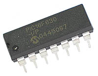
This is a development board for the PIC24F series of microchip, with:

  • USB ( plug it to any computer)
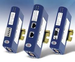
  • Ethernet ( plug it to the internet)
  • SD card ( save and read all data you will need)

I developed this thing as a learning platform, it worked ( still is). So if you always want to go a step further in microcontrollers as i want, it’s a nice way of doing it . The problem i had is that microchip examples are for their development board, which i don’t have access. So i developed my one board and examples, and i saved all the steps so it would be easier to someone to get started.Going from a simple ping to a webpage with ajax.

Just to give a head start see some of the things i have done so far with this board:

  1. An Touch keyboard, usable as a standard USB keyboard.
  2. A Video Game ( pong and snake games) , with TV output, and connection to a PC Keyboard ( the old PS/2 ) for control.
  3. Picture frame,  reads pictures form the SD card and show them on the TV.
  4. Controling a 5 volt LCD and some leds, with just 3 wires ( the MCU is 3.3V)
  5. Web server, where you can see some status of the board as temperature, the position of a Pot and a Button,  control some leds and the LCD ( all this from the internet)

And the things i know before i started ( just a checklist):

It all started when i saw this project:

web-server-on-a-business-card-part-2 ( thank you HACKADAY)

The idea of controlling something trought the internet was really nice, so i bought the chip. But when i was delivered classes started. One Year later, i started to read a promising book:

Programming 16-Bit PIC Microcontrollers in C: Learning to Fly the PIC 24 

I was the 24F, i started right away. Breadboard, wire-mess, and the first programs were running. But as i advanced in the book i felt the need for a PCB. Hackaday project was my base, but i wanted i little bit more. An USB connector, and some pins fore expansions.The WEBSD board was born.

After I developed some extra boards to plug. If i want to do a new thing with the board, just design a simple expansion board.

Follow the next pages to see more about the project. Project files are annexed on this page.

Web

Main Board

Jump this if you have no interest on the design part of the project.

The main board was been based on the hackaday project. It’s name come from the two main thing on it:

  • WEB – Internet connection
  • SD – The memory card

I was one of my first projects with a PIC24F, and the power of this chips and C combined scared me.

Layout was easy because of the PPS (Peripheral Pin Select) feature of this family. I allows the I/O of the digital peripheral to be assigned to almost any pins. But i was low on the pin count, but squeezed 4  pins out of it for expansions.

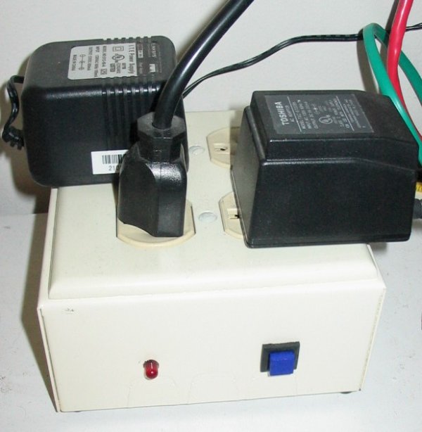
Power is done by a small power supply rated for 5v 500mA ( a standart 7805 PS). I do not chose USB power because of the current draw by the Ethernet chip.

To put all the connectors on one side , and to keep a small size, a double layer board was needed. i got addicted by smd parts, they can be faster to solder, and there is no need to drill so many holes in the board. Unfortunately i didn’t bought the Smd version of the ENC28j60 so it is a DIP part.

The MCU choice was simple, i wanted to learn to use the 24F family, USB was a nice feature to explore, SOIC package (QFN packages still frightens me). So i just pick the one with the biggest program memory.

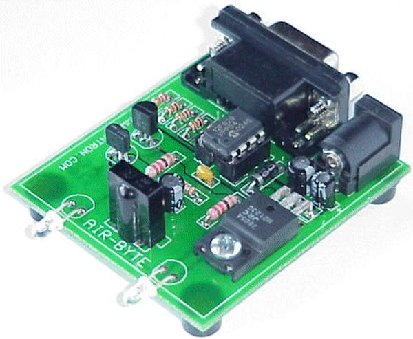
The ICSP programming connector is for the pickit2 footprint, i is used also as a rs232 serial port. You can see the communications using the terminal provided with the pickit2 or with a external serial port ( allows for more speed)

Part-list  ( with mouser reference) :

Qty Value Device Parts
3 red LEDCHIPLED_0805 LED1, LED2, LED3
8 0.1uF C-EUC0805 C2, C4, C6, C7, C9, C10, C11, C12
2 1uF C-EUC0805 C5, C8
1 2K32 R-EU_R0805 R12
2 10k R-EU_R0805 R1, R5
1 10uF CPOL-EU153CLV-0405 C3
1 25Mhz CRYSTALHC49UP Q2
2 22pf C-EUC0805 C15, C16
4 49R9 1% R-EU_R0805 R8, R9, R10, R11
1 60ohms I_0805 L1
1 330R R-EU_R0805 R4
2 330R R-EU_R0805 R2, R3
1 AP1117E33 V_REG_LM1117SOT223 IC1
1 ENC28J60-DIL ENC28J60-DIL IC2
1 J1006LONG Ethernet Connector RJ1
1 PIC24FJXXGB002 PIC24FJXXGB002 U$1
1 SD SD U$2
1 USB-MB USB-MB U$4
1 power jack JACK-PLUG1 J2

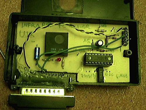
TempLedPotButton Board

Jump this if you have no interest on the design part of the project.

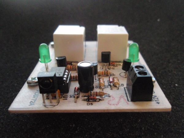
The first expansion board i designed, as simple as it can be.

I has exactly what the name says:

  • Temp – Temperature sensor, one  LM35 power from the 5v supply , which gives 10mV/°C.
  • Led –  no mystery here, a led an a resistor
  • Pot –  Potentiometer connected as a voltage divider, just waiting to be read by the ADC
  • Button – a pushbutton to the ground, no pull-ups are used as the PIC already has them.

I have i problem here in Brasil, it’s hard to get parts. I have to buy from the USA ( paying a lot of taxes , up to 200%) just to get a couple of “female headers“. So i know that the connectors i used are made for cables. Nice headers would be much better (like those in the arduino).

I was experimenting with my board manufacturer capabilities, so fell free to increase the size of those tracks ( 8mil tracks are hard with the toner transfer method).

Touch DirectKey Board

Jump this if you have no interest on the design part of the project.

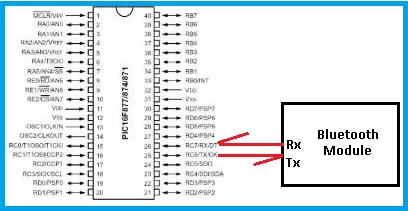
I had already  written a routine for touch sensing in assembler for the PIC16, but the 24Fs has  another nice feature the Charge Time Measurement Unit (CTMU). Using it as a current source it’s a lot easy to measure capacitance.

So a simple explanation of the touch sensors: when you put your finger close to the big square on the board you increase the parasitic capacitance of that track. The micro continually monitor the line for changes on the line detecting a button press.

No big things on this board, just a piece of acrylic on the top  to simulate the front panel of something ( i broke one corner when i was cutting). I made a simple silk screen on the board to identify the buttons. For a better performance the tracks must be as close as possible to the finger, but i put them on the bottom side of the board because if i can make it work like this, it will work well when used normally.
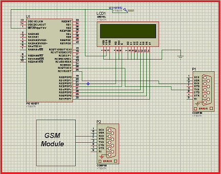
LCDSerial

Jump this if you have no interest on the design part of the project.

No development board would be complete without a LCD.But there is a big problem here, in fact two:

  • The power for this PIC is 3.3V, and all alphanumeric LCD i have at hand are only 5v. There is the possibility for connecting 5V inputs to some of the pins on the micro, but i had use all of them. ( if you take out the USB pins there isn’t enough pins left)
  • Even if it was a 5V part, i had only left 4 expansion pins, the lcd needs at least 6 ( nimble, only write mode)

So i looked around until i find the solution on a PICLIST post, i little more and i found this. One 74HCT595chip would do the job of the level conversion. I think it would be better explained by “dangerous prototypes”, so take a look over there.

But why stop on a LCD if you are using a shift register? Lets put some Leds on this thing. Another ‘595 in series and we are good to go.

The hidden position of the contrast potentiometer is worth mention. i projected with a lcd, but soldered other so it stayed in the wrong position.
LCD serial

Part-list (with mouser reference):

Qty Value Device Parts
8 LEDCHIP-LED0805 LED1, LED2, LED3, LED4, LED5, LED6, LED7, LED8
1 TAC_SWITCH S1
1 0.1uF C-EUC0805 C1
1 1K R-EU_0204/5 R2
1 10K TRIM_EU-LI10 R1
2 74HC595N 74HC595N IC1, IC2
8 330R 0805 R-EU_R0805 R3, R4, R5, R6, R7, R8, R9, R10
1 HD44780-LCD HD44780-LCD LCD1

The post WEBSD using PIC24F microcontroller appeared first on PIC Microcontroller.

IRK! Infrared Remote Controlled USB Keyboard Without Keys using PIC18F2550

$
0
0

IRK! Infrared Remote Controlled USB Keyboard Without Keys

IRK! is a USB keyboard, without keys, that you can operate just by using your LEARNINGinfrared remote control.I created it to allow me to control my MythTV home theater PC with my LEARNING infrared remote control instead of having to use a real USB keyboard – but it will work with any system (Linux, Windows, or whatever) that you can plug a USB keyboard into, and also other home theater systems like XBMC and MediaPortal.Many people use LIRC on Linux to control MythTV, but my solution does not require you to edit any complicated configuration files and does not need any special device drivers or software to be installed.IRK! is an open-hardware project that I created on SourceForge. Contributors and bug reports are welcome.Features

The feature set so far includes:

  • IRK! teaches your LEARNING remote control IR codes
  • IRK! lets you map IR codes to USB keystrokes – for example, Shift+Enter
  • IRK! sends the USB keystroke to your PC when you press a button on your remote
  • IRK! can send power off, sleep, and wake codes to your PC
  • IRK! devices can have one of 256 addresses – so you can have multiple IRK!’s
  • IRK! handles broadcasts – so multiple IRK!’s can respond to a single remote button
  • IRK! supports USB Consumer Device functions (e.g. Mute)
  • IRK! has a programmable LCD backlight delay (or ON/OFF commands)
IRK! is an evolving project. Please check out irk-usb on SourceForge for the latest enhancements.
Keyboard Without Keys

Prerequisites

This project is for reasonably advanced electronic nuts…but if you stick with it anyone can make it.

You’re going to be making a Printed Circuit Board (PCB) or at least a matrix board, soldering electronic components onto it, and then programming a PIC micro-controller, so you’ll need:

  • PCB making equipment. I use inkjet transparencies, an ordinary fluorescent desk lamp as a UV source, and Kinsten positive-acting presensitised board, and ferric chloride etchant.
  • A good soldering iron with a fine tip.
  • A micro-controller programmer able to program a Microchip PIC18F2550 micro-controller, such as a Pickit2 or you can make your own (search for “pic programmer” on Instructables).

And in case it doesn’t work for you first time, you may find it helpful to have:

  • A good logic analyser like Logic (works on Windows or Linux)
  • A USB trace capture program like USBTrace (Windows) or Wireshark (free on Linux). On Linux, make sure you’re using the libpcap 1.1 (packet capture library) or later.

Step 2: Circuit Diagram

The circuit (see pdf attachments below) can be divided into a number of functional groups.Infrared Receiver Interface
The infrared receiver consists of the TSOP4838 IR receiver module. Its job is to convert 38 kHz modulated IR signals from your remote control into digital ones and zeroes. The receiver will output a logical one (0V) when the remote is transmitting a 38 kHz signal, and will output a logical zero (+5V) during periods of silence.Infrared Transmitter Interface
The transmitter consists of a PN2222A transistor (but any general purpose NPN transistor will work) which drives a series of three Infrared Light Emitting Diodes (IR LEDs). Driving three IR LEDs is done to boost the transmitting power. Learning remotes are designed to accept signals from remote controls in close proximity and remotes are designed to produce an intense IR signal. Consequently, IRK! must produce a fairly intense IR signal in order for the learning remote to be able to “see” it during the learning process.LCD Interface
The Liquid Crystal Display is a 2×16 (2 lines at 16 characters per line) unit compatible with the Hitachi HD44780 4-bit defacto standard. You can use a 4×16, or a 4×20 display if you like as long as it is HD44780-compatible. These are available on eBay at very reasonable prices.USB Interface
The USB interface is provided by the USB module built into the PIC18F2550 microcontroller. It is managed programmatically by the USB library provided with the MikroC Pro C Compiler.

Activity LED Interface
Hardly an interface as such – a simple LED and a current-limiting resistor – but if you use a high intensity (8000 mcd) green LED then I’ve found that you can make the resistor an insanely high value – like about 18 kΩ – and the LED is still bright! That means that the driving current is only 100 uA. If you use the original 470Ω resistor specified in the circuit diagram then you could end up being startled by the brightness.

Power Interface (experimental)
The circuit diagram shows how to power the IRK! unit using the standby voltage (Vsb) output from your PC’s power supply. However, this has not been tested. You can leave the connection to Vsb out and IRK! will still work – but if you power down your system, you will not be able to power it up using your remote control. Just walk over to your PC and turn it on the old fashioned way!

IRK!.pdf(595×842) 18 KB

Parts

All parts are “through hole” (i.e. they have leads) with the exception of a single surface mount device (SMD) – a 100nF bypass capacitor.The links below are just the places I got my parts from – they’re not recommendations, but rather just a convenience for some who might not have particular bits and pieces.Parts of Keyboard
Major PartsCapacitors
2 x 4.7uF Tag Tantalum capacitor (polarised)
2 x 22pF Ceramic capacitor
1 x 220nF Tag Tantalum capacitor (polarised)
1 x 100nF Ceramic capacitor (SMD 1206 sized package)Connectors/Headers
1 x Female header 16-pin SIL (for the LCD)
1 x Male header 2×4-pin (for the PWR/RST leads)
1 x Male header 1×6-pin (for the ICSP)
1 x Male header 2×5-pin (for the USB cable)
1 x Male header 1×2-pin (for the Standby voltage lead)

Diodes
3 x 1N5817-B Schottky barrier diode (D041 package)

Integrated Circuits
1 x PIC18F2550 Microchip 18F2550 microcontroller (28-pin DIP)
1 x TSOP4838 IR Receiver and Demodulator

Liquid Crystal Display
1 x HD44780-compatible LCD Display (16×2) with backlight

Light Emitting Diodes
1 x General purpose 5 mm LED (any color)
3 x TSAL7400 Infrared LED (940 nm)

Transistors
1 x PN2222A General purpose NPN Transistor (TO92 package) (or equivalent e.g. BC548)
2 x 2N7000 General purpose N-Channel MOSFET (TO92 package)
1 x BC557B General purpose PNP Transistor (TO92 package) (or equivalent e.g. PN2907)

Resistors
1 x 100 kΩ 1/4 Watt Resistor
1 x 100 Ω 1/4 Watt Resistor
1 x 470 Ω 1/4 Watt Resistor
1 x 22 Ω 1/4 Watt Resistor
1 x 4.7 kΩ 1/4 Watt Resistor
2 x 10k Ω 1/4 Watt Resistor
1 x 4.7 kΩ 1/4 Watt Resistor
1 x 10 kΩ 1/4 Watt Resistor

Switches
7 x Tactile microswitches SPST-NO momentary action (Omron B3F series or similar)

Variable Resistors
1 x 10 kΩ Variable trimmer resistor (Bourns 3362 series or similar)

Crystals
1 x 8 MHz Crystal (HC49/S package)

Miscellaneous Parts

- Female rectangular plugs (Harwin M20-106 series) for connecting reset/power switches to the motherboard (you can usually harvest these from an old PC)
– A 5.25″ drive bay box/panel (or a standalone box) to house the assembled PCB
– Miscellaneous mounting hardware (nuts, bolts, spacers etc)

Circuit Board Making Supplies

- Kinsten double-sided PCB (preferrably fibreglass)
Kinsten DP50 developer
– Ferric Choride etchant (or whatever you normally use)

The post IRK! Infrared Remote Controlled USB Keyboard Without Keys using PIC18F2550 appeared first on PIC Microcontroller.


How to adapt a NES clone controller to bluetooth using PIC12F675

$
0
0

How to adapt a NES clone controller to bluetooth

I bought a Wireless Bluetooth RS232 TTL Transceiver Module from DX (SKU 80711) and wonder what i can do with it.

So, I’m realy nostalgic and decided to build a NES clone crontoller to bluetooth adapter, because, by this way I could play again that amazing games that we all remenber.

A important thing I need to highlight is that in my city is so dificult to find decent eletronic components and parts, so the only controller type a had in hands its the clone type, but its not complicated adapt this instructable to original NES controller.

The whole system it’s so simple, if you PC/notebook have a bluetooh card it’s done, if not you just need a Bluetooth USB dongle.

 controller

Step 1: What you need

First of all, if you’ll try to build your own NES clone to bluetooth adapter it’s supposed you have some electronics and programming skills, otherwise some steps, like the uC programming will be a little hard to do by yourself.

Components and parts list:

1 – Wireless Bluetooth RS232 TTL Transceiver Module;
1 – PIC 12F675;
1 – 5 Volts voltage regulator;
1 – 3.3 Volts voltage regulator;
2 – 1uF capacitor;
2 – 4.7 uF capacitor;
1 – 1k2 ohm resistor;
1 – 2k2 ohm resistor;
1 – 4MHz oscilator crystal;
2 – 22pF capacitor;
1 – A CC power source ( >= 8 Volts);

wire, solder wire, pic programmer, solder iron, universal circuit board, etc;

How the controller works

Well, let’s begin by the start. Let’s understand how a NES Controller function, it’s important to say that this step independs if the controller it’s the original one or the clone one, the internal functionality is the same.
Schematic controller
Internaly the controller what we call in digital eletronic parallel-to-serial register, a integrated circuit that store the state of each button (pressed or not) when a “lacth” pulse is given, then the register send each state alwaysa clock pulse is given.

So it’s cleare that the controller have 5 wire, they are: VCC, GND, LATCH, DATA, CLOCK.

So the algorithym to read the buttons states is very simple:

1 – Give a latch pulse;
2a – Verify the DATA wire;
2b – Give a clock pulse;
3 – repeat 2a and 2b  until all the buttons states were read;

Current Project / Post can also be found using:

  • pic ethernet project

The post How to adapt a NES clone controller to bluetooth using PIC12F675 appeared first on PIC Microcontroller.

Power Pic RGB with Infrared remote control using PIC12F675

$
0
0

Power Pic RGB with Infrared remote controlis a circuit that generates colors using a RGB LED and can be controlled using any infrared remote controller capable compatible with the Sony® Sirc code.

This circuit is the third evolution of Pic RGB project [1] in which the goal was to control a RGB LED and randomly generate colors. This time the goal is to use a remote control to change the colors, either by choosing a specific color or by selecting an automatic color fading mode, in which the software will keep changing colors over the color spectrum!

Infrared remote control

Design and Implementation

Like the second second evolution, (Power Pic RGB), , this project is also designed to be placed inside a white globe and drive a 3W RGB LED. The globe is available at IKEA at a price of 9.90 euros [3].

The microcontroller continues to be one of the usual PIC 12F629 or 12F675, as in the previous Pic RGB projects. To receive the infrared signal a pin with the Interrupt on Change feature is required. The circuit is very  similar to Power PIC RGB with the addition of a TSOP1738 infra red receiver.

The infrared remote controller is a Universal Remote Control Unit model URC11C-9C bought at a chinese store for about 3 euros. It is configured to emit SIRC infrared codes for Sony TV sets. In this remote controller the configuration code is 001, but other remote controllers with SIRC encoding may be used instead. Just check their configuration sheet for Sony codes and try them.

Schematic

The schematic is very similar to Power PicRGB with the addition of the infrared receiver.

From left to right we have the power supply based on a 7805 5V 1A regulator, the microcontroller, on the right the three mosfets that will drive the LED and below the TSOP1738 to receive the infrared signals. Click the image to enlarge.

Each mosfet can drive a maximum 600mA through its drain but according to Prolight each LED (red, green and blue) can only sustain 300mA which makes this mosfet perfect for the job.

Summing the 3 LED currents we get 900mA not counting the current consumed by the 7805 and the PIC itself which should around  3 or 4 mA. The 7805 is able to supply 1A of current with a proper heatsink.

Schematic Infrared remote control

The TSOP1738 infrared receiver can be replaced with any model like TSOP1238, TSOP31238, SFH5110, etc. as long as the receiving frequency is between 38Khz and 40Khz. Ideally it should be 38Khz. R5 and C4 perform some filtering on the TSOP1738 supply voltage and R4 is a pull-up to maintain GP1 at 5V when no signal is being received.


For more detail: Power Pic RGB with Infrared remote control using PIC12F675

The post Power Pic RGB with Infrared remote control using PIC12F675 appeared first on PIC Microcontroller.

Infra-Red Transmitter using PIC12F675 microcontroller

$
0
0

Description

This project uses a MicrochipPIC microcontroller and an Infra-Red LED to act as a PC controlled cable TV changer.

Infra-Red Transmitter

Operation

The purpose of this is so that my MythTVPersonal Video Recorder (PVR) can change channels on the cable TV set-top box when making a recording. A very simple program on the computer sends the channel number over RS232 to this PIC based IR transmitter which creates the correct waveform for the digits to be sent.

The cable TV box is very old and uses an unusual coding format that I haven’t seen described elsewhere and which doesn’t seem to be covered by most programmable remote controls. By capturing the signals it was possible to decode them so that the correct signals can be generated for the digits.

The function itself is very simple with just a PIC with a serial interface and an LED that is switched by a single transistor switch to provide sufficient current. I am using a very nice FTDI USB to serial converter cable (TTL-232R) that provides 5V TTL levels as well as the 5V power supply for the circuit.

Complete Unit

In this picture the box can be seen with the Infra-Red LED and a smaller red LED visible. The USB connector is at the top of the picture and has all of the RS232 converter electronics are built in to the connector which makes a very nice package.

Schematic Infra-Red Transmitter

The overall size of the box is 50 mm long, 30 mm wide and 20 mm tall.


For more detail: Infra-Red Transmitter using PIC12F675 microcontroller

Current Project / Post can also be found using:

  • single chip fm radio project

The post Infra-Red Transmitter using PIC12F675 microcontroller appeared first on PIC Microcontroller.

Build your own Wireless Network detector using PIC12F629

$
0
0

What This Is

This project is for a small electronic unit that allows the user to sense the presence and relative signal strength of wireless hotspots. It can be worn as a pendant or carried in a pocket. It is “always on” and communicates the presence and signal strength of an in-range hotspot by way of sequences of pulses – like a heartbeat you can feel. The stronger and faster the “heartbeat”, the stronger the wireless signal detected.

sensor guts illustrated

It does not actually authenticate or otherwise interact with a hotspot in any way. It is a 100% passive device, meaning it transmits nothing — it can detect hotspots, but cannot be detected itself.

How It Was Made

This project consists of a microcontroller, some custom interface electronics, a small vibe motor, and an off-the-shelf Wi-Fi detector – the one I used is by D-Link and is keychain-sized.

Here is the sensor I used, and some pictures of the construction. Details of the design will follow.

How It Works

The microcontroller periodically “presses” the button on the detector to initiate a reading. Then the microcontroller “reads” the output from the indicator LEDs on the detector, and uses this as the basis for pulsing out a signal on the vibe motor, which the wearer can feel.

In this way, the unit keeps you updated on the presence and signal strength of a wireless hotspot in your vicinity. No pulses means no signal. Short pulses means a weak signal. Faster, more frequent pulses means a stronger signal. This feedback is very much like a heartbeat, and is extremely intuitive to interpret.

How To Make Your Own

First of all, I use a microcontroller in this project. If you aren’t familiar with terms like 12F629 or .HEX files and how to blast them into a PIC, you will have trouble with this project.

The D-Link sensor I used works like this — press the button and the LEDs light up in a “scanning” pattern while it looks for a signal. It can be in this scanning pattern for up to a few seconds. Afterwards, it lights up either one, two, three, or four of the green LEDs to indicate relative signal strength. If there is no signal detected, a single red LED is lit. The LED(s) remain lit for a few seconds, then the sensor shuts off.

If your chosen sensor works differently, you will need to adjust the electronic interface and the program in the microcontroller accordingly.


For more detail: Build your own Wireless Network detector using PIC12F629

Current Project / Post can also be found using:

  • skema tda7000 varactor

The post Build your own Wireless Network detector using PIC12F629 appeared first on PIC Microcontroller.

Transmit & Receive Infrared Signals With Your PC Serial Port using PIC12F508

$
0
0

We no longer manufacture or sell the original Air-Byte IR transceiver, so we’re releasing the code & circuit design here for hobbyists and students looking to build a simple IR transceiver.

Note that the parts used here are not critical. I.E. the NPN darlington transistor driving the infrared LEDs, PNP transistor used for inverting the IR detector output, voltage regulator, LED’s, and most every other component can be replaced by something similar. However, we do have circuit boards and a full parts kit available for those who may want them.

Air-Bytea

The code or course can easily be modified to work on any PIC microcontroller.

The brain of the Air-Byte transceiver is a tiny 8-pin PIC12F508 microcontroller. Operation is simple. The PIC simply monitors GPIO,0 connected to the PC serial port TX pin #3. When this pin transitions from logic low to logic high, the 12F508 generates the 40kHz IR carrier. During low periods the carrier is suppressed.

This provides a simple method for receiving serial data on one pin, and outputting serial data on another modulated at the IR detectors band-pass frequency. Very simple, yet very effective.

The 2N3906 PNP transistor is used to invert the IR detectors data output. During idle periods, when serial data is not being received, the PC serial port RX pin should idle low. Since the idle output logic of the IR detector is logic 1, the PNP transistor inverter circuit is required. If we were to use a MAX232 RS232 to TTL level converter IC, we could eliminate the PNP inverter circuit, and connect the IR module data output directly to the MAX232.

Most PC serial ports work fine with TTL level serial data input, so we have used the direct interface to cut costs, and reduce circuit size. The 10K series resistor in series with the PC serial port TX pin and PIC serial data input pin is to limit current. This prevents damage to the PIC input from RS232 level voltage from the PC serial port. You’ll see quite a few finished products with this simple serial interface.

For more detail: Transmit & Receive Infrared Signals With Your PC Serial Port using PIC12F508

Current Project / Post can also be found using:

  • microcontroller ethernet projects
  • PİC KONTROL ETHERNET GSM
  • rs232 usb 16f877

The post Transmit & Receive Infrared Signals With Your PC Serial Port using PIC12F508 appeared first on PIC Microcontroller.

NETWORK EQUIPMENT RESETTER using PIC16F628

$
0
0

Introduction

This program is a network power resetter. It controls a solid-state-relay that is in series with 110VAC that supplies power to a satellite internet receiver, various routers, etc. Once every 24 hours it drops power for 10 seconds to allow the receiver and routers to start clean, something that seems to be necessary to keep receivers and routers from “losing themselves” after running too long!

NETWORK EQUIPMENT RESETTER

Features

This is simply an electronic solution with a couple of features, but the same thing can be accomplished by the use of a mechanical “home” timer that drops power once per day, as illustrated in the image below.

Operation

  • Power is dropped automatically for 10 seconds once every 24 hours, starting eight hours after the unit is powered up.

NETWORK EQUIPMENT RESETTER schematic

Code:

/****************************************************************************
NETWORK_RESET_01.C

This program is a network reseter.  It controls a solid-state-relay that
is in series with 110VAC.  It supplies power to a satellite receiver,
various routers, etc.  Once every 24 hours it drops power for 10 seconds
to allow the receiver and routers to start clean.

The LED flashes once per second.

The 24 hour reset occurs eight hours from the time the unit is powered on.
If it is desired to changed that delay, decide how many hours (from now)
that you want the unit to reset.  Press and hold the button for
greater than five seconds, and release it.  The LED will stop flashing.
Immediately press and hold the button until the LED starts flashing.  Count
the flashes as you hold the button.  Release the button when the LED has
flashed the number of hours you want to delay.  Normal operation will
occur after three seconds.

To drop power immediately, press and hold the button for two seconds.

                 +5
                  |
                  14
                ----------
     SW  ----6-|          |-17-- LED
               |          |-18-- SSR
               |          |
               |          |
               |  16F628  |
               |          |
               |          |-13--PROG_CLK
               |          |-12--PROG_DAT
  6MHz XTAL-15-|          |-4---MCLR
       XTAL-16-|          |     GND
                ----------
                     5
                     |
                    Gnd

***************************************************************************/


For more detail: NETWORK EQUIPMENT RESETTER using PIC16F628

Current Project / Post can also be found using:

  • Networking rooter project based on microcontroller
  • pic16 ethernet

The post NETWORK EQUIPMENT RESETTER using PIC16F628 appeared first on PIC Microcontroller.

Wireless controlled lightdimmer using PIC12F629

$
0
0

The meaning from this design is to build it in -i.e. a shaded lamp- and to switch this lamp on and off the normal way, just like it was switched before the dimmer was build in, then you could by exception dimming the lamp more or less with your TV remote control.
When you switch the power on there will follow a soft-start till the lamp burns at the previously adjusted dim level.
With the ‘0’ button in TV mode you can dim the lamp, turn more and less bright.

light dimmer
The remote control should send more then one RC5-signal per button-press seeing that the first one is ignored, this does imply that when the remote button is pressed a short time, there nothing happens.
With the P+ and P- button from a system at choice you can adjust the maximum and minimum dim-levels and with the ‘1’ button the start-up brightness.
The next time when the 230V power is switched on the lamp starts up at the adjusted dim-level.

(Re)adjust the dim-levels:
(only necessary when changing the maximum-, minimum- or start-up- level)
First you should select an unused system on your remote control, i.e. SAT, AMP, VCR2 or DCC mode.

Adjust maximum level: Keep, while switching the power on, the P+ button from the remote control pressed and wait until the lamp burns on desired maximum level.

Adjust minimum level: Keep, while switching the power on, the P- button from the remote control pressed and wait until the lamp burns on desired minimum level. Recommended is to adjust the minimum dim level not to “lamp off” level, because then it’s easy to forget to switch the power off and use unnecessary power.

Adjust start-up level: Keep, while switching the power on, the ‘0’ button from your remote control pressed and wait until the lamp burns on desired level.

Re-adjust the default values (reset): Keep, while switching the power on, the MUTE button from the remote control pressed.

During adjusting the dim-levels, the dim-level changes slower then normal to make adjusting easier.
When letting the button loose and the adjustment is ok, the red- en green LED blinks for a while.
With the -for the dimmer reserved- system selected on the remote control, the P+ (dim-level up) / P- (dim-level down) and button ‘0’ (up/down turn by turn) works too.
Button ‘1’ dims directly to the adjusted start-up level.
Which system on the remote control is choosen doesn’t matter, the ‘0’ button works always in the TV-mode too.

Above described applies to the here downloadable .BAS and .HEX examples, but you can ofcourse modify it to your own wishes.
Keep in mind that a remote control does not always send that what you expected.
The volume from TV, SAT, VCR1 and VCR2 are all the same.
Just as the volumegroup from TAPE, TUNER, CD, etc.
And the ‘0’-‘9’ buttons from system TAPE for example send nothing at all.

See the lists: RC5 system codes and RC5 command codes


For more detail: Wireless controlled lightdimmer using PIC12F629

Current Project / Post can also be found using:

  • pic microcontrol home project
  • interfacing microcontroller with internet
  • home automation proteus
  • pic project ethernet

The post Wireless controlled lightdimmer using PIC12F629 appeared first on PIC Microcontroller.


2-Channel IR Relay Controller for PIC10F200

$
0
0

Description

This project is a 2 channel infrared (IR) remote controlled relay driver with power saving.  It works with 12-bit SIRC IR signals as used by Sony remote controls.

The controller also features a power save feature which reduces the relay holding voltage to 50% of the relays nominal operating voltage once the relay has switched on.

IR Relay Controller

The board uses Microchip’s low cost PIC10F200 microcontroller along with a handful of easy to find  components making this possibly the lowest cost remote controlled relay driver around.  Everything you need to know to build this project, including the firmware code is right here on the project page.

Don’t forget to check out the accompanying mini IR remote control which can be used with this project.

Download schematic in PDF

Circuit Description

The board requires a 12 volt DC supply input.  This is fed through diode D5 which provides protection from a reversed connection of the power supply. Capacitor C2 is used for decoupling the supply.  The 5 volt supply needed by the microcontroller U1 and the IR receiver U2 is generated using a simple zener shunt regulator comprising R6 and the 5.1 volt Zener diode D4.

The relays are switched on by microcontroller U1 via driver transistors Q1 and Q4.  These are low power NPN transistors, in this case BC547 but virtually any small NPN transistor will work here as they only need to switch around 30mA – BC548 or BC549 would also work well.  Diodes D1 and D2 provide protection for the transistors against the back EMF voltage transient when the relays are switched off.

The controller also features a power saving control which reduces the power consumption of the relays by around 50% when they are on.  Relays of the type used here typically need 75% of their nominal voltage to “pull-in”, once on they will ‘hold’ with a lower voltage.  The datasheet for the Omron G5LE for example shows a must release voltage of 10% of rated voltage – for a 12V relay that’s around 1.2V.  This circuit uses a holding voltage of around 50% or 6 Volts.

Normally the supply voltage is fed to the relay coils via zener diode D3 which drops 5.1 volts leaving around 6 volts across the relay coil. In parallel with D3 is transistor Q2.  When this transistor is switched on, it bypasses D3 and provides the full supply voltage to the relays.  This ‘boost’ voltage is switched by the microcontroller with Q2 being switched on via Q3.  The firmware in the microcontroller detects when a relay is being turned on and applies the boost for a minimum of around 100mS, again the datasheet for the relays gives typical operate time of 10mS, so the 100mS boost guarantees the relay will pull-in before the voltage is reduced.  If you find the relay used doesn’t hold fully swap D3 for a 4.7 volt zener.

LEDs 1 and 2 are connected across the relay coils to give visual indication when the relays are on and can be omitted if not required.

The circuit is controlled by U1, a PIC10F200, the smallest and cheapest PIC available from Microchip.  The IR signal is detected and demodulated by U2 a TSOP4838 IR receiver IC.  This part was chosen because it has a low supply current requirement – typically around 1.5mA – making it ideal for use with the shunt regulator.  The output from the TSOP4838 is active low, when a signal is received the output goes to 0V, when no signal is received it is pulled high by an internal pull-up resistor.  The signal is decoded using the firmware programmed into the PIC10F200.  This has been written to decode the 12-bit SIRC protocol (see download section)

I recently had an email from someone asking why I used the TSOP4838 38Khz transceiver when the Sony SIRC protocol use a 40KHz carrier. It was a good question and the answer is that I source a lot of my parts from Rapid Electronics and they only stock the TSOP4838.   In practice this part will work just fine with a 40Khz IR signal.  However, if you can get hold of the TSOP4840 (40KHz variant) by all means use it.

For more information on the SIRC infrared protocol and codes see:

If you don’t want the power save feature, replace D3 with a wire link and omit R2,R3,R5,Q2 and Q3.


For more detail: 2-Channel IR Relay Controller for PIC10F200

Current Project / Post can also be found using:

  • onli pic lan com
  • pic of lan

The post 2-Channel IR Relay Controller for PIC10F200 appeared first on PIC Microcontroller.

SPI to 4 x UART Bridge (MULTIUART)

$
0
0

If your a fan of electronics then you like me will often find it annoying on the lack of hardware serial ports on modern devices. Many modules like the Wifi ESP8266 and the Bluetooth HC-06 are available for peanuts but they each require a UART based serial peripheral on your controller to work effectively. In fact a huge range of external electronics can be added to your system via a serial UART connection: GPS, GSM (mobile phone), RFID, RS232, LIN, Ethernet, Zigbee, Modbus, DMX, 4D systems graphical LCDs to name a few more.

Most modern microcontrollers and devices like the Raspberry Pi have at least one serial UART peripheral so you can do a lot with these devices. However now and then you need to combine several communications style modules together into a single design. A recent project I undertook was a mobile alarm system which used Bluetooth proximity to arm / disarm the system, GPS to track the location, Accelerometer to track movement and GSM based SMS messages to inform the owner where their item is.SPI to 4 x UART Bridge (MULTIUART)

The Arduino Mega 2560 offers two serial UART peripherals but what if that is not enough or you need something more affordable for mass production. To move to a different chip may mean rewriting your entire code so is there an easier way?

These modern microcontrollers commonly also feature a peripheral named SPI which is typically a lot faster then a UART based serial peripheral and can be used to talk to multiple devices by use of individual chip select signals from the controller. If the controller does not have an SPI peripheral then it can simply be driven using a bit banged software approach using standard I/O pins with no major downfalls. By using the SPI interface and my design you can communicate with up to four serial UART peripherals simultaneously.

Here is a guide to recreate and build my SPI to 4 x UART bridge for use in your own projects. If you don’t want to make your own then I also have a limited number of assembled boards available.

Step 1: The schematic

The circuit for the board is pretty basic as we are simply using a larger 16-bit PIC micro controller to do most of the work for us.

U1 is the PIC24FJ64GA306 micro controller, I chose this chip because it has four UART peripherals and was the cheapest I could find by shopping around on Farnell and microchipdirect. The chip also features several 5V tolerant I/O pins meaning that even though the device will need to be powered at 3.3V it will work as is with 5V systems.

C1 is a 10uF ceramic capacitor and is required by the micro controller to maintain the internal processor voltage levels. This capacitor need to be placed close to the VCAP pin.

C2, C3, C4 and C5 are 100nF ceramic capacitors to provide some voltage smoothing and noise rejection to allow the micro controller to run reliably. These capacitor need to be placed close to the VSS and VDD pins of the micro controller.

R1 provides the MCLR reset signal allowing the micro controller to run. R2 pulls the chip select signal high by default so the SPI interface is automatically disabled until driven low by the host. R3 is a current limiting diode to drive the communications indicator LED.

J1 is the interface to the host controller. It provides connections such as power (3.3V) and ground as well as the four standard SPI pins (MOSI, MISO, SCK and CS). J2 is the interface to the four serial UART peripherals. J3 is the in circuit serial programming (ICSP) header designed to work with the PICkit 3 programming tool.

Note that if your designing your own board then you might want to include other features to be accessed via the SPI interface.

Step 2: The bill of materials

Here is a list of the materials I used in the project.

  • 1 x PIC24FJ64GA306
  • 2 x 8 way SIL headers 2.54mm pitch
  • 2 x 10K Resistor
  • 1 x 330R Resistor
  • 1 x 10uF Ceramic Cap
  • 4 x 100nF Ceramic Cap
  • 1 x LED
  • 1 x PCB

Also required for the build

  • 1 x PICkit 3 programmer
  • 1 x 6 way SIL header 2.54mm pitch
  • Host controller with SPI interface for testing (I used an ECIO28P from MatrixTSL, an Arduino would also be fine)SPI to 4 x UART Bridge (MULTIUART) schematic

Step 3: The PCB

The PCB was created using Proteus and standard 0805 sized surface mount components. Eagle would work just as well if you are familiar with that.

The PCB design was exported as a series of Gerber files and manufactured using Eurocircuits. The Gerber files are attached in the zip file.

The trick with Eurocircuits is to order in bulk to bring down the price per board. So make sure your circuitry is correct before submitting your design. Of course any other PCB manufacturer should also be able to work with the Gerber files.

I ordered my PCBs with a top layer surface mount mask to make the manufacturing process easier. I created a jig for the PCBs to sit in by using my trusty CNC machine to create a pocket in a piece of MDF. The pocket needs a small cut out to ensure you can get it out of the hole easily. I placed a PCB into the pocket and used this to line up the solder paste mask. Once the mask is in place use tape to secure one side of the mask to the MDF. This creates a hinge so you can easily lift up the mask to add or remove the PCBs.

To create the code to drive the CNC I used SketchUp to draw a square the size of my PCB. I then added a small slot to make removing the PCB from the pocket easier. The file was then saved and exported as a .dxf CAD file. I then used the LazyCAM software to convert the .dxf file into G-code which will drive my CNC machine.


For more detail: SPI to 4 x UART Bridge (MULTIUART)

Current Project / Post can also be found using:

  • Connecting pic 16f877a microcontroller to internet
  • microcontroller with ethernet switch
  • pic microcontroller ethernet tutorial

The post SPI to 4 x UART Bridge (MULTIUART) appeared first on PIC Microcontroller.

Universal Serial Infrared Receiver using PIC16F88

$
0
0

You can use this Universal Infrared Receiver (UIR) project to control your PC:

  •  Starting Windows programs,
  •  setting the Windows volume control,
  •  even moving the mouse around the screen!

All at the touch of a button – with your TV remote control in fact!

It uses a PIC microcontroller to characterize the demodulated infrared signal and then transmit it as a serial data stream to the PC.

Software running on the PC recognizes data stream for each key press (in fact the PC software has to learn the data stream for each key press) and activates the program (or event) that you specify.  Since the software can learn each key press you can use it with any remote control  e.g. TV, video, DVD, satellite etc.  

Universal Serial Infrared Receiver

It’s even good with multiple remotes so you could use any one of a set of remotes to control the PC

Specification for Serial Infrared receiver project.

Baud Rate 57600 Baud
Clock Internal 8Mhz 
Remove Control type Any (Point any control at it and let the PC software learn its codes).


Note: Some remote controls need two key presses (if you press the same key) as they output an inverted key sequence for a repeated key.  If you press a different key then it works as a normal remote.

How the Serial Infrared receiver works

This project uses a standard Infrared detector module (one of those 3 pin devices) as the main input.

It’s not worth making your own circuit up as it will not match the performance of a three pin demodulator module.

I had a go using some circuits I found on the web and but these use a PIN diode and a high impedance amplifier e.g. LM3140 – but the circuits are actually light meters and saturate when a light shines on them  (even desk lamp) – so they become insensitive to the IR light – the PIN diode reacts to any light source.  You can get some use out of them up to about six feet but a lot of engineering has gone into the three pin modules so it really is worth using them and they are very cheap.

Inside the module is a PIN diode, AGC circuit, band pass filter, control logic and output detector.  The datasheet specifies use from 15m (45ft) up to possibly 30m (90ft) max!. These are very good detectors that are also insensitive to sunlight (has a physical filter over the PIN diode and the electronic bandpass filter).

Serial Infrared receiver 

How the Serial Infrared receiver works.

This project took longer than it should have and I have ended up with a far smaller source code than my initial attempts!  First off I used the capture facility in the CCP and the Timer1 timer to accurately measure each period of high and low decoded IR.  This turned out to be too accurate!

IR signal codes decoding accuracy

You don’t need accuracy in this project – IR codes are designed not to need accurate measurement and if you attempt it slight variations in the edge positions or measuring accuracy cause the output numbers to change.  Since the decoder software in the PC relies on a repeatable data stream (with slight variation) this method does not work.

IR signals are designed so that you can sample them but this requires that you know the code sequence (or encoding e.g. RC5) in advance so that you can time from the start sequence to the exact middle of a bit position.

Since this project allows you to use any remote control unit, the encoding sequence can not be known in advance, so the the solution is to sample the remote control sequence at a high frequency.  

The problem is that if you start decoding from the first rising edge then errors accumulate due to slight variations in the remote control output (or the sampling edge occurs at the same time as an input transition) causing a random data stream output which can not reliably be decoded by the PC software.

IR decode solution

The solution is to sample the input data starting from each rising and falling edge where a bit measurement period counter (period counter) is reset.  At each sample point (here it is about 50us) the period counter is incremented.  This gives a number that represents the period of each high or low part of the signal. 

The 50us sample period is about ten times the expected signal period (IR codes generally use 500us minimum period) so this gives a good period measurement.

Note that the period counter is 8 bits long so that for long input sequences (high or low) the counter wraps around – this does not matter since the period counter will always produce the same value for the same input sequence and this is what the PC decoder software is looking for.


For more detail: Universal Serial Infrared Receiver using PIC16F88

Current Project / Post can also be found using:

  • pic ethernet tutorial
  • signal lan net projects
  • microcontroller over ethernet
  • pic microcontroller internet connection tutorial

The post Universal Serial Infrared Receiver using PIC16F88 appeared first on PIC Microcontroller.

Connect Ethernet controller with PIC Code

$
0
0
The ENC28J60 is a stand-alone Ethernet controller with an industry standard Serial Peripheral Interface (SPI). It is designed to serve as an Ethernet network interface for any controller equipped with SPI.
The ENC28J60 meets all of the IEEE 802.3 specifications. It incorporates a number of packet filtering schemes to limit incoming packets. It also provides an internal DMA module for fast data throughput and hardware assisted IP checksum calculations. Communication with the host controller is implemented via two interrupt pins and the SPI, with data rates of up to 10 Mb/s. Two dedicated pins are used for LED link and network activity indication.
This library is designed to simplify handling of the underlying hardware (ENC28J60). It works with any PIC with integrated SPI and more than 4 Kb ROM memory. 38 to 40 MHz clock is recommended to get from 8 to 10 Mhz SPI clock, otherwise PIC should be clocked by ENC28J60 clock output due to its silicon bug in SPI hardware. If you try lower PIC clock speed, there might be board hang or miss some requests.
SPI Ethernet ENC28J60 Library supports:

  • IPv4 protocol.
  • ARP requests.
  • ICMP echo requests.
  • UDP requests.
  • TCP requests (no stack, no packet reconstruction).
  • ARP client with cache.
  • DNS client.
  • UDP client.
  • DHCP client.
  • packet fragmentation is NOT supported.

  Important :

  • Due to PIC16 RAM/Flash limitations PIC16 library does NOT have ARP, DNS, UDP and DHCP client support implemented.
  • Global library variable SPI_Ethernet_userTimerSec is used to keep track of time for all client implementations (ARP, DNS, UDP and DHCP). It is user responsibility to increment this variable each second in it’s code if any of the clients is used.
  • For advanced users there are header files ("__EthEnc28j60.h" and "__EthEnc28j60Private.h") in Uses\P16 and Uses\P18 folders of the compiler with description of all routines and global variables, relevant to the user, implemented in the SPI Ethernet ENC28J60 Library.
  • The appropriate hardware SPI module must be initialized before using any of the SPI Ethernet ENC28J60 library routines.
  • For MCUs with two SPI modules it is possible to initialize both of them and then switch by using the SPI_Set_Active() routine.Connect Ethernet controller with PIC Code

Library Dependency Tree

External dependencies of SPI Ethernet ENC28J60 Library

The following variables must be defined in all projects using SPI Ethernet ENC28J60 Library: Description: Examples :
extern sfr sbit SPI_Ethernet_CS; ENC28J60 chip select pin. sbit SPI_Ethernet_CS at RC1_bit;
extern sfr sbit SPI_Ethernet_RST; ENC28J60 reset pin. sbit SPI_Ethernet_Rst at RC0_bit;
extern sfr sbit SPI_Ethernet_CS_Direction; Direction of the ENC28J60 chip select pin. sbit SPI_Ethernet_CS_Direction at TRISC1_bit;
extern sfr sbit SPI_Ethernet_RST_Direction; Direction of the ENC28J60 reset pin. sbit SPI_Ethernet_Rst_Direction at TRISC0_bit;
The following routines must be defined in all project using SPI Ethernet ENC28J60 Library: Description: Examples :
unsigned int SPI_Ethernet_UserTCP(unsigned char *remoteHost, unsigned int remotePort, unsigned int localPort, unsigned int reqLength, TEthPktFlags *flags); TCP request handler. Refer to the library example at the bottom of this page for code implementation.
unsigned int SPI_Ethernet_UserUDP(unsigned char *remoteHost, unsigned int remotePort, unsigned int localPort, unsigned int reqLength, TEthPktFlags *flags); UDP request handler. Refer to the library example at the bottom of this page for code implementation.

Library Routines

PIC16 and PIC18:

  • SPI_Ethernet_Init
  • SPI_Ethernet_Enable
  • SPI_Ethernet_Disable
  • SPI_Ethernet_doPacket
  • SPI_Ethernet_putByte
  • SPI_Ethernet_putBytes
  • SPI_Ethernet_putString
  • SPI_Ethernet_putConstString
  • SPI_Ethernet_putConstBytes
  • SPI_Ethernet_getByte
  • SPI_Ethernet_getBytes
  • SPI_Ethernet_UserTCP
  • SPI_Ethernet_UserUDP

PIC18 Only:

  • SPI_Ethernet_getIpAddress
  • SPI_Ethernet_getGwIpAddress
  • SPI_Ethernet_getDnsIpAddress
  • SPI_Ethernet_getIpMask
  • SPI_Ethernet_confNetwork
  • SPI_Ethernet_arpResolve
  • SPI_Ethernet_sendUDP
  • SPI_Ethernet_dnsResolve
  • SPI_Ethernet_initDHCP
  • SPI_Ethernet_doDHCPLeaseTime
  • SPI_Ethernet_renewDHCP

SPI_Ethernet_Init

Prototype void SPI_Ethernet_Init(unsigned char *mac, unsigned char *ip, unsigned char fullDuplex);
Returns Nothing.
Description This is MAC module routine. It initializes ENC28J60 controller. This function is internaly splited into 2 parts to help linker when coming short of memory.
ENC28J60 controller settings (parameters not mentioned here are set to default):
  • receive buffer start address : 0x0000.
  • receive buffer end address : 0x19AD.
  • transmit buffer start address: 0x19AE.
  • transmit buffer end address : 0x1FFF.
  • RAM buffer read/write pointers in auto-increment mode.
  • receive filters set to default: CRC + MAC Unicast + MAC Broadcast in OR mode.
  • flow control with TX and RX pause frames in full duplex mode.
  • frames are padded to 60 bytes + CRC.
  • maximum packet size is set to 1518.
  • Back-to-Back Inter-Packet Gap: 0x15 in full duplex mode; 0x12 in half duplex mode.
  • Non-Back-to-Back Inter-Packet Gap: 0x0012 in full duplex mode; 0x0C12 in half duplex mode.
  • Collision window is set to 63 in half duplex mode to accomodate some ENC28J60 revisions silicon bugs.
  • CLKOUT output is disabled to reduce EMI generation.
  • half duplex loopback disabled.
  • LED configuration: default (LEDA-link status, LEDB-link activity).

Parameters:

  • mac: RAM buffer containing valid MAC address.
  • ip: RAM buffer containing valid IP address.
  • fullDuplex: ethernet duplex mode switch. Valid values: 0 (half duplex mode) and 1 (full duplex mode).
Requires Global variables :
  • SPI_Ethernet_CS: Chip Select line
  • SPI_Ethernet_CS_Direction: Direction of the Chip Select pin
  • SPI_Ethernet_RST: Reset line
  • SPI_Ethernet_RST_Direction: Direction of the Reset pin

must be defined before using this function.
The SPI module needs to be initialized. See the SPIx_Init and SPIx_Init_Advanced routines.

Example
#define SPI_Ethernet_HALFDUPLEX     0
#define SPI_Ethernet_FULLDUPLEX     1

// mE ethernet NIC pinout
sfr sbit SPI_Ethernet_Rst at RC0_bit;
sfr sbit SPI_Ethernet_CS  at RC1_bit;
sfr sbit SPI_Ethernet_Rst_Direction at TRISC0_bit;
sfr sbit SPI_Ethernet_CS_Direction  at TRISC1_bit;
// end ethernet NIC definitions

unsigned char myMacAddr[6] = {0x00, 0x14, 0xA5, 0x76, 0x19, 0x3f}; // my MAC address 
unsigned char myIpAddr     = {192, 168,   1, 60 };  // my IP addr

SPI1_Init(); 
SPI_Ethernet_Init(myMacAddr, myIpAddr, SPI_Ethernet_FULLDUPLEX);

SPI_Ethernet_Enable

Prototype void SPI_Ethernet_Enable(unsigned char enFlt);
Returns Nothing.
Description This is MAC module routine. This routine enables appropriate network traffic on the ENC28J60 module by the means of it’s receive filters (unicast, multicast, broadcast, crc). Specific type of network traffic will be enabled if a corresponding bit of this routine’s input parameter is set. Therefore, more than one type of network traffic can be enabled at the same time. For this purpose, predefined library constants (see the table below) can be ORed to form appropriate input value.
Parameters:
  • enFlt: network traffic/receive filter flags. Each bit corresponds to the appropriate network traffic/receive filter:
    Bit Mask Description Predefined library const
    0 0x01 MAC Broadcast traffic/receive filter flag. When set, MAC broadcast traffic will be enabled. _SPI_Ethernet_BROADCAST
    1 0x02 MAC Multicast traffic/receive filter flag. When set, MAC multicast traffic will be enabled. _SPI_Ethernet_MULTICAST
    2 0x04 not used none
    3 0x08 not used none
    4 0x10 not used none
    5 0x20 CRC check flag. When set, packets with invalid CRC field will be discarded. _SPI_Ethernet_CRC
    6 0x40 not used none
    7 0x80 MAC Unicast traffic/receive filter flag. When set, MAC unicast traffic will be enabled. _SPI_Ethernet_UNICAST

      Note :

    • Advanced filtering available in the ENC28J60 module such as Pattern Match, Magic Packet and Hash Table can not be enabled by this routine. Additionaly, all filters, except CRC, enabled with this routine will work in OR mode, which means that packet will be received if any of the enabled filters accepts it.
    • This routine will change receive filter configuration on-the-fly. It will not, in any way, mess with enabling/disabling receive/transmit logic or any other part of the ENC28J60 module. The ENC28J60 module should be properly cofigured by the means of SPI_Ethernet_Init routine.
Requires Ethernet module has to be initialized. See SPI_Ethernet_Init.
Example
SPI_Ethernet_Enable(_SPI_Ethernet_CRC | _SPI_Ethernet_UNICAST); // enable CRC checking and Unicast traffic

SPI_Ethernet_Disable

Prototype void SPI_Ethernet_Disable(unsigned char disFlt);
Returns Nothing.
Description This is MAC module routine. This routine disables appropriate network traffic on the ENC28J60 module by the means of it’s receive filters (unicast, multicast, broadcast, crc). Specific type of network traffic will be disabled if a corresponding bit of this routine’s input parameter is set. Therefore, more than one type of network traffic can be disabled at the same time. For this purpose, predefined library constants (see the table below) can be ORed to form appropriate input value.
Parameters:
  • disFlt: network traffic/receive filter flags. Each bit corresponds to the appropriate network traffic/receive filter:
    Bit Mask Description Predefined library const
    0 0x01 MAC Broadcast traffic/receive filter flag. When set, MAC broadcast traffic will be disabled. _SPI_Ethernet_BROADCAST
    1 0x02 MAC Multicast traffic/receive filter flag. When set, MAC multicast traffic will be disabled. _SPI_Ethernet_MULTICAST
    2 0x04 not used none
    3 0x08 not used none
    4 0x10 not used none
    5 0x20 CRC check flag. When set, CRC check will be disabled and packets with invalid CRC field will be accepted. _SPI_Ethernet_CRC
    6 0x40 not used none
    7 0x80 MAC Unicast traffic/receive filter flag. When set, MAC unicast traffic will be disabled. _SPI_Ethernet_UNICAST

      Note :

    • Advanced filtering available in the ENC28J60 module such as Pattern Match, Magic Packet and Hash Table can not be disabled by this routine.
    • This routine will change receive filter configuration on-the-fly. It will not, in any way, mess with enabling/disabling receive/transmit logic or any other part of the ENC28J60 module.
    • The ENC28J60 module should be properly cofigured by the means of SPI_Ethernet_Init routine.
Requires Ethernet module has to be initialized.
Example
SPI_Ethernet_Disable(_SPI_Ethernet_CRC | _SPI_Ethernet_UNICAST); // disable CRC checking and Unicast traffic

SPI_Ethernet_doPacket

Prototype unsigned char SPI_Ethernet_doPacket();
Returns
  • 0 – upon successful packet processing (zero packets received or received packet processed successfully).
  • 1 – upon reception error or receive buffer corruption. ENC28J60 controller needs to be restarted.
  • 2 – received packet was not sent to us (not our IP, nor IP broadcast address).
  • 3 – received IP packet was not IPv4.
  • 4 – received packet was of type unknown to the library.
Description This is MAC module routine. It processes next received packet if such exists. Packets are processed in the following manner:
  • ARP & ICMP requests are replied automatically.
  • upon TCP request the SPI_Ethernet_UserTCP function is called for further processing.
  • upon UDP request the SPI_Ethernet_UserUDP function is called for further processing.
  Note : SPI_Ethernet_doPacket must be called as often as possible in user’s code.
Requires Ethernet module has to be initialized.
Example
if (SPI_Ethernet_doPacket() == 0)(1) {  // process received packets
  ...
}

SPI_Ethernet_putByte

Prototype void SPI_Ethernet_putByte(unsigned char v);
Returns Nothing.
Description This is MAC module routine. It stores one byte to address pointed by the current ENC28J60 write pointer (EWRPT).
Parameters:
  • v: value to store
Requires Ethernet module has to be initialized.
Example
char data_;
...
SPI_Ethernet_putByte(data); // put an byte into ENC28J60 buffer

SPI_Ethernet_putBytes

Prototype void SPI_Ethernet_putBytes(unsigned char *ptr, unsigned int n);
Returns Nothing.
Description This is MAC module routine. It stores requested number of bytes into ENC28J60 RAM starting from current ENC28J60 write pointer (EWRPT) location.
Parameters:
  • ptr: RAM buffer containing bytes to be written into ENC28J60 RAM.
  • n: number of bytes to be written.
Requires Ethernet module has to be initialized.
Example
char *buffer =  "mikroElektronika";  
...
SPI_Ethernet_putBytes(buffer, 16); // put an RAM array into ENC28J60 buffer

SPI_Ethernet_putConstBytes

Prototype void SPI_Ethernet_putConstBytes(const unsigned char *ptr, unsigned int n);
Returns Nothing.
Description This is MAC module routine. It stores requested number of const bytes into ENC28J60 RAM starting from current ENC28J60 write pointer (EWRPT) location.
Parameters:
  • ptr: const buffer containing bytes to be written into ENC28J60 RAM.
  • n: number of bytes to be written.
Requires Ethernet module has to be initialized.
Example
const char *buffer =  "mikroElektronika";  
...
SPI_Ethernet_putConstBytes(buffer, 16); // put a const array into ENC28J60 buffer

SPI_Ethernet_putString

Prototype unsigned int SPI_Ethernet_putString(unsigned char *ptr);
Returns Number of bytes written into ENC28J60 RAM.
Description This is MAC module routine. It stores whole string (excluding null termination) into ENC28J60 RAM starting from current ENC28J60 write pointer (EWRPT) location.
Parameters:
  • ptr: string to be written into ENC28J60 RAM.
Requires Ethernet module has to be initialized.
Example
char *buffer =  "mikroElektronika";  
...
SPI_Ethernet_putString(buffer); // put a RAM string into ENC28J60 buffer

SPI_Ethernet_putConstString

Prototype unsigned int SPI_Ethernet_putConstString(const unsigned char *ptr);
Returns Number of bytes written into ENC28J60 RAM.
Description This is MAC module routine. It stores whole const string (excluding null termination) into ENC28J60 RAM starting from current ENC28J60 write pointer (EWRPT) location.
Parameters:
  • ptr: const string to be written into ENC28J60 RAM.
Requires Ethernet module has to be initialized.
Example
const char *buffer =  "mikroElektronika"; 
...
SPI_Ethernet_putConstString(buffer); // put a const string into ENC28J60 buffer

SPI_Ethernet_getByte

Prototype unsigned char SPI_Ethernet_getByte();
Returns Byte read from ENC28J60 RAM.
Description This is MAC module routine. It fetches a byte from address pointed to by current ENC28J60 read pointer (ERDPT).
Requires Ethernet module has to be initialized.
Example
char buffer; 
...
buffer = SPI_Ethernet_getByte(); // read a byte from ENC28J60 buffer

SPI_Ethernet_getBytes

Prototype void SPI_Ethernet_getBytes(unsigned char *ptr, unsigned int addr, unsigned int n);
Returns Nothing.
Description This is MAC module routine. It fetches equested number of bytes from ENC28J60 RAM starting from given address. If value of 0xFFFF is passed as the address parameter, the reading will start from current ENC28J60 read pointer (ERDPT) location.
Parameters:
  • ptr: buffer for storing bytes read from ENC28J60 RAM.
  • addr: ENC28J60 RAM start address. Valid values: 0..8192.
  • n: number of bytes to be read.
Requires Ethernet module has to be initialized.
Example
char buffer[16];  
...
SPI_Ethernet_getBytes(buffer, 0x100, 16); // read 16 bytes, starting from address 0x100

SPI_Ethernet_UserTCP

Prototype unsigned int SPI_Ethernet_UserTCP(unsigned char *remoteHost, unsigned int remotePort, unsigned int localPort, unsigned int reqLength, TEthPktFlags *flags);
Returns
  • 0 – there should not be a reply to the request.
  • Length of TCP/HTTP reply data field – otherwise.
Description This is TCP module routine. It is internally called by the library. The user accesses to the TCP/HTTP request by using some of the SPI_Ethernet_get routines. The user puts data in the transmit buffer by using some of the SPI_Ethernet_put routines. The function must return the length in bytes of the TCP/HTTP reply, or 0 if there is nothing to transmit. If there is no need to reply to the TCP/HTTP requests, just define this function with return(0) as a single statement.
Parameters:
  • remoteHost: client’s IP address.
  • remotePort: client’s TCP port.
  • localPort: port to which the request is sent.
  • reqLength: TCP/HTTP request data field length.
  • flags: structure consisted of two bit fields :
    typedef struct {
      unsigned canCloseTCP: 1;  // flag which closes socket
      unsigned isBroadcast: 1;  // flag which denotes that the IP package has been received via subnet broadcast address (not used for PIC16 family)
    } TEthPktFlags;
    
  Note : The function source code is provided with appropriate example projects. The code should be adjusted by the user to achieve desired reply.
Requires Ethernet module has to be initialized.
Example This function is internally called by the library and should not be called by the user’s code.

SPI_Ethernet_UserUDP

Prototype unsigned int SPI_Ethernet_UserUDP(unsigned char *remoteHost, unsigned int remotePort, unsigned int destPort, unsigned int reqLength, TEthPktFlags *flags);
Returns
  • 0 – there should not be a reply to the request.
  • Length of UDP reply data field – otherwise.
Description This is UDP module routine. It is internally called by the library. The user accesses to the UDP request by using some of the SPI_Ethernet_get routines. The user puts data in the transmit buffer by using some of the SPI_Ethernet_put routines. The function must return the length in bytes of the UDP reply, or 0 if nothing to transmit. If you don’t need to reply to the UDP requests, just define this function with a return(0) as single statement.
Parameters:
  • remoteHost: client’s IP address.
  • remotePort: client’s port.
  • destPort: port to which the request is sent.
  • flags: structure consisted of two bit fields :
    typedef struct {
      unsigned canCloseTCP: 1;  // flag which closes TCP socket (not relevant to UDP)
      unsigned isBroadcast: 1;  // flag which denotes that the IP package has been received via subnet broadcast address (not used for PIC16 family)
    } TEthPktFlags;
    
      Note : The function source code is provided with appropriate example projects. The code should be adjusted by the user to achieve desired reply.
Requires Ethernet module has to be initialized.
Example This function is internally called by the library and should not be called by the user’s code.

SPI_Ethernet_getIpAddress

Prototype unsigned char * SPI_Ethernet_getIpAddress();
Returns Pointer to the global variable holding IP address.
Description This routine should be used when DHCP server is present on the network to fetch assigned IP address.
  Note : User should always copy the IP address from the RAM location returned by this routine into it’s own IP address buffer. These locations should not be altered by the user in any case!
Requires Ethernet module has to be initialized.
Available for PIC18 family MCUs only.
Example
unsigned char ipAddr[4];  // user IP address buffer
... 
memcpy(ipAddr, SPI_Ethernet_getIpAddress(), 4); // fetch IP address

SPI_Ethernet_getGwIpAddress

Prototype unsigned char * SPI_Ethernet_getGwIpAddress();
Returns Pointer to the global variable holding gateway IP address.
Description This routine should be used when DHCP server is present on the network to fetch assigned gateway IP address.
  Note : User should always copy the IP address from the RAM location returned by this routine into it’s own gateway IP address buffer. These locations should not be altered by the user in any case!
Requires Ethernet module has to be initialized.
Available for PIC18 family MCUs only.
Example
unsigned char gwIpAddr[4];  // user gateway IP address buffer
... 
memcpy(gwIpAddr, SPI_Ethernet_getGwIpAddress(), 4); // fetch gateway IP address 

SPI_Ethernet_getDnsIpAddress

Prototype unsigned char * SPI_Ethernet_getDnsIpAddress()
Returns Pointer to the global variable holding DNS IP address.
Description his routine should be used when DHCP server is present on the network to fetch assigned DNS IP address.
  Note : User should always copy the IP address from the RAM location returned by this routine into it’s own DNS IP address buffer. These locations should not be altered by the user in any case!
Requires Ethernet module has to be initialized.
Available for PIC18 family MCUs only.
Example
unsigned char dnsIpAddr[4];  // user DNS IP address buffer
... 
memcpy(dnsIpAddr, SPI_Ethernet_getDnsIpAddress(), 4); // fetch DNS server address 

Connect Ethernet controller with PIC Code schematich

SPI_Ethernet_getIpMask

Prototype unsigned char * SPI_Ethernet_getIpMask()
Returns Pointer to the global variable holding IP subnet mask.
Description This routine should be used when DHCP server is present on the network to fetch assigned IP subnet mask.
  Note : User should always copy the IP address from the RAM location returned by this routine into it’s own IP subnet mask buffer. These locations should not be altered by the user in any case!
Requires Ethernet module has to be initialized.
Available for PIC18 family MCUs only.
Example
unsigned char IpMask[4];  // user IP subnet mask buffer
... 
memcpy(IpMask, SPI_Ethernet_getIpMask(), 4); // fetch IP subnet mask

SPI_Ethernet_confNetwork

Prototype void SPI_Ethernet_confNetwork(char *ipMask, char *gwIpAddr, char *dnsIpAddr);
Returns Nothing.
Description Configures network parameters (IP subnet mask, gateway IP address, DNS IP address) when DHCP is not used.
Parameters:
  • ipMask: IP subnet mask.
  • gwIpAddr gateway IP address.
  • dnsIpAddr: DNS IP address.


For more detail: Connect Ethernet controller with PIC Code

The post Connect Ethernet controller with PIC Code appeared first on PIC Microcontroller.

Connect CAN Protocol with PIC

$
0
0
The mikroC PRO for PIC provides a library (driver) for working with the CAN module.
The CAN is a very robust protocol that has error detection and signalization, self–checking and fault confinement. Faulty CAN data and remote frames are re-transmitted automatically, similar to the Ethernet.
Data transfer rates depends on the distance. For example, 1 Mbit/s can be achieved at network lengths below 40m while 250 Kbit/s can be achieved at network lengths below 250m. The greater distance the lower maximum bitrate that can be achieved. The lowest bitrate defined by the standard is 200Kbit/s. Cables used are shielded twisted pairs.
CAN supports two message formats:
  • Standard format, with 11 identifier bits, and
  • Extended format, with 29 identifier bits
  Important :
  • Consult the CAN standard about CAN bus termination resistance.


Library Routines

  • CANSetOperationMode
  • CANGetOperationMode
  • CANInitialize
  • CANSetBaudRate
  • CANSetMask
  • CANSetFilter
  • CANRead
  • CANWrite
  • CANSetTxIdleLevelConnect CAN Protocol with PIC

CANSetOperationMode

Prototype void CANSetOperationMode(unsigned short mode, unsigned short wait_flag);
Returns Nothing.
Description Sets CAN to requested mode, i.e. copies mode to CANSTAT. Parameter mode needs to be one of CAN_OP_MODE constants .
Parameter wait_flag needs to be either 0 or 0xFF:
  • If set to 0xFF, this is a blocking call – the function won’t “return” until the requested mode is set.
  • If 0, this is a non-blocking call. It does not verify if CAN module is switched to requested mode or not. Caller must use CANGetOperationMode to verify correct operation mode before performing mode specific operation.
Requires Microcontroller must be connected to CAN transceiver (MCP2551 or similar) which is connected to CAN bus.
Example
CANSetOperationMode(_CAN_MODE_CONFIG, 0xFF);

CANGetOperationMode

Prototype unsigned short CANGetOperationMode();
Returns Current opmode.
Description Function returns current operational mode of CAN module.
Requires Microcontroller must be connected to CAN transceiver (MCP2551 or similar) which is connected to CAN bus.
Example
if (CANGetOperationMode() == _CAN_MODE_NORMAL) { ... };

CANInitialize

Prototype void CANInitialize(char SJW, char BRP, char PHSEG1, char PHSEG2, char PROPSEG, char CAN_CONFIG_FLAGS);
Returns Nothing.
Description Initializes CAN. All pending transmissions are aborted. Sets all mask registers to 0 to allow all messages.
Filter registers are set according to flag value:
if (CAN_CONFIG_FLAGS & _CAN_CONFIG_VALID_XTD_MSG != 0)
  // Set all filters to XTD_MSG
else if (config & _CAN_CONFIG_VALID_STD_MSG != 0)
  // Set all filters to STD_MSG
else
  // Set half of the filters to STD, and the rest to XTD_MSG.

Parameters:

  • SJW as defined in datasheet (1–4)
  • BRP as defined in datasheet (1–64)
  • PHSEG1 as defined in datasheet (1–8)
  • PHSEG2 as defined in datasheet (1–8)
  • PROPSEG as defined in datasheet (1–8)
  • CAN_CONFIG_FLAGS is formed from predefined constants
Requires CAN must be in Config mode; otherwise the function will be ignored.
Microcontroller must be connected to CAN transceiver (MCP2551 or similar) which is connected to CAN bus.
Example
init = _CAN_CONFIG_SAMPLE_THRICE &
       _CAN_CONFIG_PHSEG2_PRG_ON &
       _CAN_CONFIG_STD_MSG       &
       _CAN_CONFIG_DBL_BUFFER_ON &
       _CAN_CONFIG_VALID_XTD_MSG &
       _CAN_CONFIG_LINE_FILTER_OFF;
...
CANInitialize(1, 1, 3, 3, 1, init);   // initialize CAN

CANSetBaudRate

Prototype void CANSetBaudRate(char SJW, char BRP, char PHSEG1, char PHSEG2, char PROPSEG, char CAN_CONFIG_FLAGS);
Returns Nothing.
Description Sets CAN baud rate. Due to complexity of CAN protocol, you cannot simply force a bps value. Instead, use this function when CAN is in Config mode. Refer to datasheet for details.
Parameters:
  • SJW as defined in datasheet (1–4)
  • BRP as defined in datasheet (1–64)
  • PHSEG1 as defined in datasheet (1–8)
  • PHSEG2 as defined in datasheet (1–8)
  • PROPSEG as defined in datasheet (1–8)
  • CAN_CONFIG_FLAGS is formed from predefined constants
Requires CAN must be in Config mode; otherwise the function will be ignored.
Microcontroller must be connected to CAN transceiver (MCP2551 or similar) which is connected to CAN bus.
Example
init = _CAN_CONFIG_SAMPLE_THRICE &
       _CAN_CONFIG_PHSEG2_PRG_ON &
       _CAN_CONFIG_STD_MSG       &
       _CAN_CONFIG_DBL_BUFFER_ON &
       _CAN_CONFIG_VALID_XTD_MSG &
       _CAN_CONFIG_LINE_FILTER_OFF;
...
CANSetBaudRate(1, 1, 3, 3, 1, init);

CANSetMask

Prototype void CANSetMask(char CAN_MASK, long value, char CAN_CONFIG_FLAGS);
Returns Nothing.
Description Function sets mask for advanced filtering of messages. Given value is bit adjusted to appropriate buffer mask registers.
Parameters:
  • CAN_MASK is one of predefined constant values
  • value is the mask register value
  • CAN_CONFIG_FLAGS selects type of message to filter, either _CAN_CONFIG_XTD_MSG or _CAN_CONFIG_STD_MSG
Requires CAN must be in Config mode; otherwise the function will be ignored.
Microcontroller must be connected to CAN transceiver (MCP2551 or similar) which is connected to CAN bus.
Example
// Set all mask bits to 1, i.e. all filtered bits are relevant:
CANSetMask(_CAN_MASK_B1, -1, _CAN_CONFIG_XTD_MSG);

// Note that -1 is just a cheaper way to write 0xFFFFFFFF.
   Complement will do the trick and fill it up with ones.

CANSetFilter

Prototype void CANSetFilter(char CAN_FILTER, long value, char CAN_CONFIG_FLAGS);
Returns Nothing.
Description Function sets message filter. Given value is bit adjusted to appropriate buffer mask registers.
Parameters:
  • CAN_FILTER is one of predefined constant values
  • value is the filter register value
  • CAN_CONFIG_FLAGS selects type of message to filter, either _CAN_CONFIG_XTD_MSG or _CAN_CONFIG_STD_MSG
Requires CAN must be in Config mode; otherwise the function will be ignored.
Microcontroller must be connected to CAN transceiver (MCP2551 or similar) which is connected to CAN bus.
Example
// Set id of filter B1_F1 to 3:
CANSetFilter(_CAN_FILTER_B1_F1, 3, _CAN_CONFIG_XTD_MSG);

CANRead

Prototype char CANRead(long *id, char *data, char *datalen, char *CAN_RX_MSG_FLAGS);
Returns Message from receive buffer or zero if no message found.
Description Function reads message from receive buffer. If at least one full receive buffer is found, it is extracted and returned. If none found, function returns zero.
Parameters:
  • id is message identifier
  • data is an array of bytes up to 8 bytes in length
  • datalen is data length, from 1–8.
  • CAN_RX_MSG_FLAGS is value formed from constants
Requires CAN must be in mode in which receiving is possible.
Microcontroller must be connected to CAN transceiver (MCP2551 or similar) which is connected to CAN bus.
Example
char rcv, rx, len, data[8];
long id;

// ...
rx = 0;
// ...
rcv = CANRead(id, data, len, rx);

CANWrite

Prototype unsigned short CANWrite(long id, char *data, char datalen, char CAN_TX_MSG_FLAGS);
Returns Returns zero if message cannot be queued (buffer full).
Description If at least one empty transmit buffer is found, function sends message on queue for transmission. If buffer is full, function returns 0.
Parameters:
  • id is CAN message identifier. Only 11 or 29 bits may be used depending on message type (standard or extended)
  • data is array of bytes up to 8 bytes in length
  • datalen is data length from 1–8
  • CAN_TX_MSG_FLAGS is value formed from constants
Requires CAN must be in Normal mode.
Microcontroller must be connected to CAN transceiver (MCP2551 or similar) which is connected to CAN bus.
Example
char tx, data;
long id;

// ...
tx = _CAN_TX_PRIORITY_0 &
     _CAN_TX_XTD_FRAME;
// ...
CANWrite(id, data, 2, tx);

CANSetTxIdleLevel

Prototype void CANSetTxIdleLevel(char driveHighState);
Returns Nothing.
Description This function sets the state of CANTX pin when recessive.
Parameters:
  • driveHighState: State of the CANTX pin. Valid values :
    Description Predefined library const
    CANTX pin will drive VDD when recessive.
    Use it when using a differential bus to avoid signal crosstalk in CANTX from other nearby pins.
    _CAN_DRIVE_HIGH_STATE_ENABLE
    CANTX pin will be tri-state when recessive. _CAN_DRIVE_HIGH_STATE_DISABLE
Requires Microcontroller must be connected to CAN transceiver (MCP2551 or similar) which is connected to CAN bus.
Example
CANSetTxIdleLevel(_CAN_DRIVE_HIGH_STATE_ENABLE);

CAN Constants

There is a number of constants predefined in CAN library. To be able to use the library effectively, you need to be familiar with these. You might want to check the example at the end of the chapter.

CAN_OP_MODE

CAN_OP_MODE constants define CAN operation mode. Function CANSetOperationMode expects one of these as its argument:
const char
_CAN_MODE_BITS = 0xE0, // Use this to access opmode bits
_CAN_MODE_NORMAL = 0x00,
    _CAN_MODE_SLEEP  = 0x20,
_CAN_MODE_LISTEN = 0x60,
    _CAN_MODE_LOOP   = 0x40,
Connect CAN Protocol with PIC schematich_CAN_MODE_CONFIG = 0x80;
CAN_CONFIG_FLAGS
CAN_CONFIG_FLAGS constants define flags related to CAN module configuration. Functions CANInitialize and CANSetBaudRate expect one of these (or a bitwise combination) as their argument:
const char
_CAN_CONFIG_DEFAULT = 0xFF, // 11111111
_CAN_CONFIG_PHSEG2_PRG_BIT = 0x01,
_CAN_CONFIG_PHSEG2_PRG_ON = 0xFF, // XXXXXXX1
_CAN_CONFIG_PHSEG2_PRG_OFF = 0xFE, // XXXXXXX0
_CAN_CONFIG_LINE_FILTER_BIT = 0x02,
_CAN_CONFIG_LINE_FILTER_ON = 0xFF, // XXXXXX1X
_CAN_CONFIG_LINE_FILTER_OFF = 0xFD, // XXXXXX0X
_CAN_CONFIG_SAMPLE_BIT = 0x04,
_CAN_CONFIG_SAMPLE_ONCE = 0xFF, // XXXXX1XX
_CAN_CONFIG_SAMPLE_THRICE = 0xFB, // XXXXX0XX
_CAN_CONFIG_MSG_TYPE_BIT = 0x08,
_CAN_CONFIG_STD_MSG = 0xFF, // XXXX1XXX
_CAN_CONFIG_XTD_MSG = 0xF7, // XXXX0XXX
_CAN_CONFIG_DBL_BUFFER_BIT = 0x10,
_CAN_CONFIG_DBL_BUFFER_ON = 0xFF, // XXX1XXXX
_CAN_CONFIG_DBL_BUFFER_OFF = 0xEF, // XXX0XXXX
_CAN_CONFIG_MSG_BITS = 0x60,
_CAN_CONFIG_ALL_MSG = 0xFF, // X11XXXXX
_CAN_CONFIG_VALID_XTD_MSG = 0xDF, // X10XXXXX
_CAN_CONFIG_VALID_STD_MSG = 0xBF, // X01XXXXX
_CAN_CONFIG_ALL_VALID_MSG = 0x9F; // X00XXXXX
You may use bitwise AND (&) to form config byte out of these values. For example:
init = _CAN_CONFIG_SAMPLE_THRICE &
       _CAN_CONFIG_PHSEG2_PRG_ON &
_CAN_CONFIG_DBL_BUFFER_ON &
_CAN_CONFIG_STD_MSG       &
       _CAN_CONFIG_VALID_XTD_MSG &


For more detail: Connect CAN Protocol with PIC

Current Project / Post can also be found using:

  • create a long distance bus with pic microcontroller
  • pic mikrocontroller lan

The post Connect CAN Protocol with PIC appeared first on PIC Microcontroller.

Viewing all 60 articles
Browse latest View live


<script src="https://jsc.adskeeper.com/r/s/rssing.com.1596347.js" async> </script>